Author: tz61

  • Build ECE391 Env on Win64

    On Msys2 MINGW64

    cf. https://wiki.qemu.org/Hosts/W32

    pacman -S mingw-w64-x86_64-gcc mingw-w64-x86_64-glib2 mingw-w64-x86_64-gettext-runtime mingw-w64-x86_64-gcc mingw-w64-x86_64-binutils mingw-w64-x86_64-pixman mingw-w64-x86_64-SDL2 mingw-w64-x86_64-gtk3 mingw-w64-x86_64-riscv64-unknown-elf-gcc mingw-w64-x86_64-gdb-multiarch git diffutils zsh vim)

    Please enable Developer Mode to support soft link without Administrator permission, otherwise it prompts

    Found ninja-1.12.1 at D:/msys64/usr/bin/ninja.exe
    Running postconf script 'D:/ZJUI/ECE391/qemu/build/pyvenv/bin/python3.exe D:/ZJUI/ECE391/qemu/scripts/symlink-install-tree.py'
    Please enable Developer Mode to support soft link without Administrator permission
    error making symbolic link D:/msys64/opt/toolchains/riscv/lib/libfdt.a
    Traceback (most recent call last):
      File "D:/ZJUI/ECE391/qemu/scripts/symlink-install-tree.py", line 35, in <module>
        raise e
      File "D:/ZJUI/ECE391/qemu/scripts/symlink-install-tree.py", line 28, in <module>
        os.symlink(source, bundle_dest)
    OSError: [WinError 1314] 客户端没有所需的特权。: 'D:/ZJUI/ECE391/qemu/build/subprojects/dtc/libfdt/libfdt.a' -> 'qemu-bundle/msys64/opt/toolchains/riscv/lib/libfdt.a'
    

    ./configure --prefix=/opt/toolchains/riscv --target-list=riscv32-softmmu,riscv64-softmmu --enable-gtk --enable-system --disable-werror
    make -j
    make install

    Change zsh for MINGW session https://superuser.com/questions/961699/change-default-shell-on-msys2

    sh -c "$(curl -fsSL https://raw.githubusercontent.com/ohmyzsh/ohmyzsh/master/tools/install.sh)"

    Set in mingw64.ini:

    SHELL=/usr/bin/zsh

    There is no PTS on windows so use telnet instead
    source:https://www.uni-koeln.de/~pbogusze/posts/QEMU_serial_console.html

    qemu-system-riscv64 -machine virt -bios none -kernel cp1.elf -m 8M -nographic -serial mon:stdio -serial telnet:localhost:4321,server,nowait

    Add D:\msys64\mingw64\bin to PATH of Windows
    Then telnet to attach to con1

    telnet localhost 4321
  • [RISC-V ECE391]MP2

    Some Programming/Reference Manuals

    • Volume 1, Unprivileged Specification version 20240411 PDF GitHub
    • Volume 2, Privileged Specification version 20240411 PDF GitHub
    • PLIC Specs v1.0.0
      For newest PLIC manual please refer to https://riscv.org/technical/specifications/ and https://github.com/riscv/riscv-plic-spec/releases
    • NS16550 UART(Texus Instrument)
      cf. Section 8.6 for register specification.

      Note on CSR instructions

      CSR can’t be accessed directly, thus those instructions are needed.
      Only 6 instructions, CSR[RS,RC,RW,RSI,RCI,RWI],I is immediate.
      S for set, C for clear, W for write, other mnemonic(e.g. CSRR/CSRW) are pseudo-instructions with either rs1=x0 or ds=x0.
      For both CSRRS and CSRRC, if rs1=x0, then the instruction will not write to the CSR at all
      For both CSRRSI and CSRRCI, if uimm[4:0] field is zero, then the instruction will not write to the CSR at all
      But CAVEAT LECTOR!, if rs1=x0 or uimm[4:0]=0 for CSRRW or CSRRWI, then csr will be CLEARED

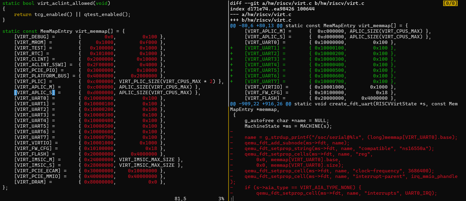
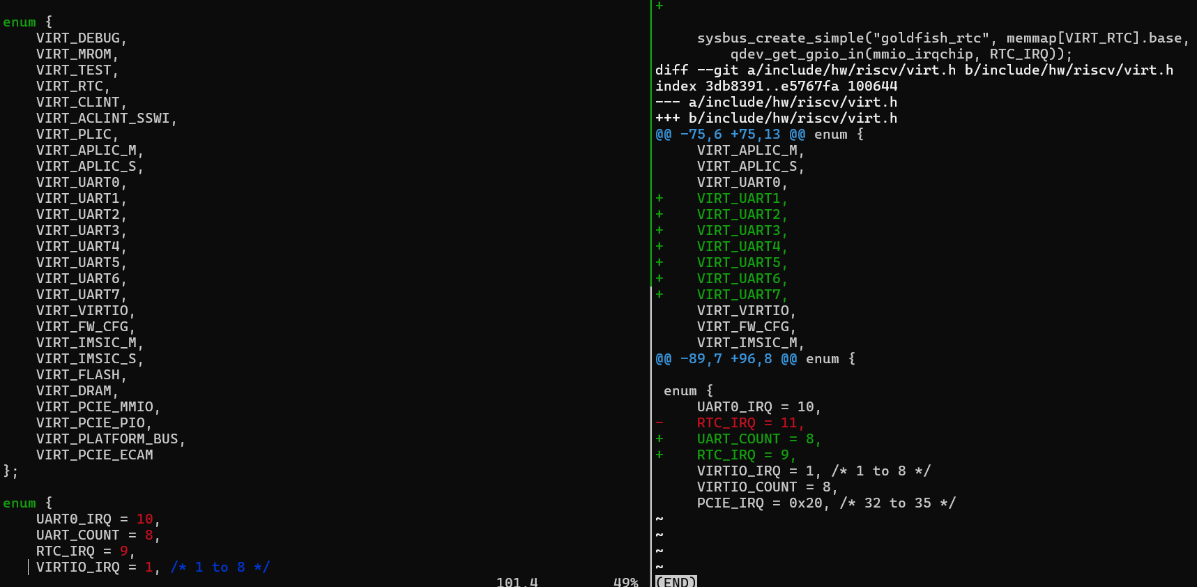
      IRQ number(PLIC source no./id) and MMAP(Memory Mapping) in ECE391 FA24

      It is modified based on https://github.com/qemu/qemu/blob/master/hw/riscv/virt.c
      7 uarts are added and IRQ number of RTC is moved to 9

      Ext ASM in C code

      Reference How to Use Inline Assembly Language in C Code

    • Do not expect a sequence of asm statements to remain perfectly consecutive after compilation, even when you are using the volatile qualifier. If certain instructions need to remain consecutive in the output, put them in a single multi-instruction asm statement.
    • \n\t to seperate assembly instructions in a single Assembly Template
      Input: using , delimiter

      [ [asmSymbolicName] ] constraint (cexpression)

      Output:

      [ [asmSymbolicName] ] constraint (cvariablename)
    • asmSymbolicName
      Specifies a symbolic name for the operand. Reference the name in the assembler template by enclosing it in square brackets (i.e. %[Value]). The scope of the name is the asm statement that contains the definition. Any valid C variable name is acceptable, including names already defined in the surrounding code. No two operands within the same asm statement can use the same symbolic name.
      When not using an asmSymbolicName, use the (zero-based) position of the operand in the list of operands in the assembler template. For example if there are two output operands and three inputs, use %2 in the template to refer to the first input operand, %3 for the second, and %4 for the third.

    For example

    uint32_t Mask = 1234;
    uint32_t Index;
    asm ("bsfl %[aMask], %[aIndex]"
         : [aIndex] "=r" (Index)
         : [aMask] "r" (Mask)
         : "cc");

    if no asmSymbolicName

    __asm__ ("btsl %2,%1\n\t" // Turn on zero-based bit #Offset in Base.
             "sbb %0,%0"      // Use the CF to calculate old.
       : "=r" (old), "+rm" (*Base)
       : "Ir" (Offset)
       : "cc");
    return old;

    output registers begin with 0, the number of input regs are after output regs.

    If using I(immediate) as constraint, the input value must be known at assembly time or later.

    Control Status Registers(CSR)

    mstatus:
    mip:
    mie:
    mtvec:
    mcause:
    mepc:

    PLIC

    Each source has a priority(0 is disabled, higher for high prio).
    destination is a contex, which is a HART combined with mode(M/S)
    every context (e.g. context 0) has a source enable(not prio).
    PLIC Indicates which interrupt source raised the interrupt by

    Trap entry

    • Places current PC into mepc CSR
    • Sets mstatus.MPP to previous privilege mode (current privilege mode is decided by path)
    • Sets mstatus.MPIE to mstatus.MIE
    • Sets mstatus.MIE to 0 (interrupts disabled on entry)
    • Sets PC to mtvec.BASE (if mode 0) or mtvec.BASE + 4×cause

      Trap exit

    • Sets mstatus.mie to mstatus.MPP ; sets MPIE to 1
    • Changes privilege mode to mstatus.MPP; sets MPP to 0
    • Set PC to mepc
      You will get to the vector addr of Externel M-Mode Interrupt(mtvec[1:0]==2b’01) or just BASE(mtvec[1:0]==2b’00), then check which source issued the interrupt, then go to the corresponding ISR(interrupt service routine) or what so-called interrupt handler.
      A CPU claims the interrupt to identify source
    • CPU reads special per-context claim register on PLIC
    • PLIC returns highest priority source number on read
    • PLIC will not offer the interrupt source to other CPUs
    • CPU has committed to servicing it
      CPU can always read claim register to poll for highest priority interrupt

      End procedure for PLIC(Interrupt Completion)

      When CPU is finished servicing the itnerrupt, it signals completion to the PLIC

    • CPU writes source number to its claim register on PLIC
    • This indicates CPU is done servicing the interrupt source
  • vscode添加RISC-V调试支持

    vscode 前置

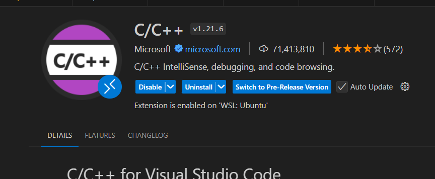
    1. 安装C/C++插件
    2. 开启Allow Breakpoints Everywhere Vscode 在汇编文件中添加调试断点
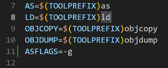
    3. Makefile中添加ASFLAGS = -g

      vscode文件设置

      在workspace下.vscode下新建启动文件与任务文件launch.json, tasks.json

      launch.json

      miDebuggerPath 填riscv-gdb绝对路径,program填要调的程序

      {
      // Use IntelliSense to learn about possible attributes.
      // Hover to view descriptions of existing attributes.
      // For more information, visit: https://go.microsoft.com/fwlink/?linkid=830387
      "version": "0.2.0",
      "configurations": [
          {
              "name": "Debug RISC-V",
              "type": "cppdbg",
              "request": "launch",
              "program":"${workspaceFolder}/demo.elf",
              "cwd": "${workspaceFolder}",
              "miDebuggerPath": "/opt/toolchains/riscv/bin/riscv64-unknown-elf-gdb",
              "miDebuggerServerAddress": "localhost:1234",
              "stopOnEntry": true,
              "preLaunchTask": "Run QEMU"
          }
      ]
      }

      tasks.json

    command中修改调试器启动参数,修改对应启动elf文件。不要删除前面的一条命令echo 'QEMU started',这个是为了让vscode结束启动等待用

    {
        // See https://go.microsoft.com/fwlink/?LinkId=733558
        // for the documentation about the tasks.json format
        "version": "2.0.0",
        "tasks": [
            {
                "label": "Build",
                "type": "shell",
                "command": "make",
                "args": [
                    ""
                ],
                "group": {
                    "kind": "build",
                    "isDefault": true
                },
                "problemMatcher": [
                    "$gcc"
                ]
            },
            {
                "label": "Run QEMU",
                "type": "shell",
                "command": "echo 'QEMU started';qemu-system-riscv64 -s -S -machine virt -bios none -kernel demo.elf -m 128M -serial mon:stdio -device bochs-display",
                "dependsOn": ["Build"],
                "args": [],
                "group": {
                    "kind": "test",
                    "isDefault": true
                },
                "isBackground": true,
                "problemMatcher": [
                    {
                        "pattern": [
                            {
                                "regexp": ".",
                                "file": 1,
                                "location": 2,
                                "message": 3
                            }
                        ],
                        "background": {
                            "activeOnStart": true,
                            "beginsPattern": ".",
                            "endsPattern": ".",
                        }
                    }
                ]
            }
        ]
    }
  • 焊接RK3566心得以及usb otg改host

    焊接3566,用14S镊子轻推,看到旁边丝印线在动就够了,丝印线0.12mm,刚好不会推多,植锡0.12mm厚度钢网完全够用
    usb otg改hostRK3566 AndroidR usb otg host和peripheral切换软件手动切换,写/sys/devices/platform/fe8a0000.usb2-phy/otg_mode

  • AMD Xilinx FPGA XC7S50-CSGA324开发日志

    ZYNQ 7010

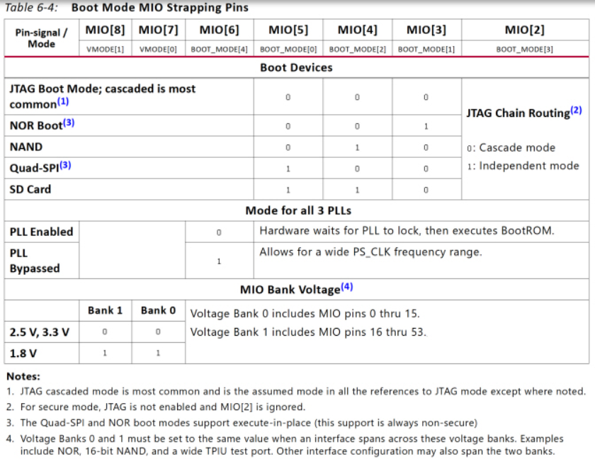
    Boot mode

    https://docs.amd.com/r/en-US/ug585-zynq-7000-SoC-TRM/Boot-Mode-Pin-Settings

    From zdyz:

    Note that can only boot from SD0

    Can I boot from SD1 port in Zynq 7000?

    Hardware rasterizer

    https://www.youtube.com/watch?v=9eydUJl_dRQ, https://github.com/fpgarevolution/FlyingCubes3D/tree/main?tab=readme-ov-file
    using PYNQ-Z1(XC7Z020CLG400) Sch

    采用flyby拓扑

    看了文档PS DDRC支持auto training(write leveling), https://docs.amd.com/r/en-US/ug585-zynq-7000-SoC-TRM/DRAM-Training
    写了`Successful training depends on providing an approximate minimum DQS to CLK delay value. This value should be estimated based on system board layout as well as package delay information.
    CK 比DQS长就行,可以看ZYBO的指示,它们CK比DQS短,因此导致了negative CK-to-DQS的error.https://digilent.com/reference/programmable-logic/zybo-z7/reference-manual 关于PS DDRC delay怎么设置可以参考他们的board file
    https://www.amobbs.com/thread-5684869-1-1.html 里面说

    本帖最后由 dr2001 于 2017-12-15 08:21 编辑
    Zynq的DDR3链路训练是自动的,不用人工介入;默认CLK组要比数据组长。
    有特殊情况,算好延迟填写好有利于链路训练收敛(或加速收敛)。寄存器可以看链路训练结果,如果链路特殊的话,请查看验证。

    DDR3 layout reference

    本来是打算自己画的结果太难了,layout有问题,拉线就非常困难
    zynq7010/7020核心板众筹openzynq(单片)
    sdr5ZYNQ 和 DDR3 的 4 层板(双片四层)

    画画心得

    1. 先别等长T to src
    2. T to src,T to ddr拉完后,设置Spacing8mil规则然后开始修T to ddr(以最长的为target),不用担心最外面的过孔和线距离不到8mil,后面会修完
    3. 两片ddr分开点,中间空多点
    4. 中间不够长(横线等长),就往两边借道
    5. 如果原来的网络有T点,你原理图加了个R到Vtt,那么记得在改新规则(SigXplorer)后把原来的T点unschedule了(在net schedule里),不然会变黄,还得把R连好线
    6. T点不能是,比如这个板子的odt,三个线同时连R,所以拓扑上没有T点
    7. 电源fanout 用8mil

      关于pindelay

      最后忘记做pindelay等长了,具体做法:https://www.eet-china.com/mp/a163664.html, https://adaptivesupport.amd.com/s/question/0D52E00006hpkbgSAA/ddr-chip-package-delay?language=en_US
      但我看harbor的板子,clk_n 离最大网络差300mil,加上pindelay(A12,1457-1287 +(579-316)=433mil), 就没管了,反正jlc没有Pindelay功能。以后再说吧,先把final做了,不然周末没完没了了

      Spartan-7 XC7S50

      HDMI

      关于50Ohm 上拉,TMDS电平是3V3的,但看https://community.element14.com/technologies/fpga-group/b/blog/posts/arty-s7—imaging-system-part-3-adding-a-physical-hdmi-port-to-arty-s7 这篇文章感觉不用上拉也行.
      然后HR Bank都支持TMDS IO,只要这个bank用3V3供电,具体参考ug471_7Series_SelectIO.

      Download program to SPI Flash

      包括如何改SPI programming 速率,等等
      一开始load慢是因为SPI x1 + 3Mhz导致的,本质上是修改xdc文件

      set_property BITSTREAM.GENERAL.COMPRESS TRUE [current_design]
      set_property CONFIG_MODE SPIx4 [current_design]
      set_property BITSTREAM.CONFIG.CONFIGRATE 33 [current_design]

      https://www.instructables.com/Flashing-a-MicroBlaze-Program/

      Spartan-MIG7

    8. IO管脚定义规则(DQ,ADDR,CMD等) Zynq 7000 SoC and 7 Series Devices Memory Interface Solutions User Guide (UG586)

      System clock input

      The system clock input must be in the same column as the memory interface. The system clock input is recommended to be in the address/control bank, when possible.
      Recommended: Although the MIG allows system clock selection to be in different super logic regions (SLRs), it is not recommended due to the additional clock jitter in this topology.

      可以从different SLR(bank) 输入时钟,Narvi 7 Spartan就是这么做的,但是urbana board 在bank35放了一个100mhz差分时钟.
      最好还是放一个在Bank35.
      MIG 7 Series FPGAs DDR3/DDR2 – Clocking Guidelines and43185 – MIG 7 Series – Requirement of System Clock Input 说clk 必须在同一列的bank内
      但是在Vivado: Two Clock Wizard ports with same settings?里面有人说说,只要pass了MIG的customize,任何一个clk都行,甚至从clk wizard.

    SPI Nor flash选型

    W25Q128 BV FV JV(BV FV都停产了,最新的是JV)
    原版用的是MT25QL128,然后spartan 7 支持winbond家的见AMD-Xilinx-UG908的Spartan 7 Configuration Memory Devices

    Xilinx Vivado ISE无法启动调试器服务器hw_server

    https://zhuanlan.zhihu.com/p/670343325
    原因是windows保留了默认端口3121,去掉就行

    Xilinx 烧录器参考

    FT2232H

    1.支持串口的高速Xilinx下载器-FT2232H,自制Xilinx JTAG仿真器
    2.参考Urbana Board

    FT232H

    TT_Digilent_JTAG_HS2
    自制Xilinx JTAG仿真器

    烧录方法

    本质上是烧录到eeprom 93LC56B里面

    1. program_ftdi
      基于FT2232集成USB直接实现XilinxJTAG和UART串口
      Programming FTDI Devices for Vivado Hardware Manager Support
      可以无脑烧录FT232H和FT2232H,FT4232H
      2.还有FTDI官方的FT_PROG也可以烧录,还可以保存设置复制到另一个设备上
      视频FT2232HL制作JTAG下载器驱动安装教程
      3.此外针对FT2232H还有Digilent的售后工具:DigilentFTDIConfig.exe

      ch347F

      使用USB转JTAG芯片CH347在Vivado下调试
      xvcd-ch347
      https://github.com/pengwon/ch347-hs-usb-bridge
      https://www.bilibili.com/video/BV1uH4y1j7Py
      WCH在CH347F实现了Xilinx Virtual Cable
      关于Altera的,参考这个https://oshwhub.com/bitshen/usb-blaster

  • 【每周学习摘要20(24/07/25-24/07/31)】

    在新的buildroot(2302)上面交叉编译Mplayer-1.5

    ./configure --cc=arm-rockchip830-linux-uclibcgnueabihf-gcc --enable-cross-compile --strip=arm-rockchip830-linux-uclibcgnueabihf-strip --target=arm-linux --enable-alsa --enable-fbdev --prefix=/home/ztn/Embedded/RK/luckfox-pico/sysdrv/source/buildroot/buildroot-2023.02.6/output/target/usr --extra-ldflags=-L/home/ztn/Embedded/RK/luckfox-pico/sysdrv/source/buildroot/buildroot-2023.02.6/output/host/arm-buildroot-linux-uclibcgnueabihf/sysroot/usr/lib --extra-cflags=-I/home/ztn/Embedded/RK/luckfox-pico/sysdrv/source/buildroot/buildroot-2023.02.6/output/host/arm-buildroot-linux-uclibcgnueabihf/sysroot/usr/include

    然后

    make -j && make install

    buildroot的output下面的host/sysroot 是包含include和lib的sysroot,全部由交叉编译器生成,所以不用担心和ubuntu-base的一样,生成的binary(例如glibc)源头的编译器和目前使用的编译器不一致.
    我觉得有必要学习LFS(Linux from scratch), 这样就能知道glibc或ulibc怎么编译的,包括核心组件比如ls, pwd这些,看8. Chapter 5: Compiling a Cross-Toolchain – How to build Linux From Scratch (LFS) 12.1 Tutorial

    conda更新后crash

    C:\Users\tz61>conda activate
    Traceback (most recent call last):
      File "D:\miniconda3\Lib\site-packages\conda\exception_handler.py", line 18, in __call__
        return func(*args, **kwargs)
               ^^^^^^^^^^^^^^^^^^^^^
      File "D:\miniconda3\Lib\site-packages\conda\cli\main.py", line 96, in main_sourced
        from ..base.context import context
      File "D:\miniconda3\Lib\site-packages\conda\base\context.py", line 31, in <module>
        from ..common._os.linux import linux_get_libc_version
      File "D:\miniconda3\Lib\site-packages\conda\common\_os\__init__.py", line 8, in <module>
        from .windows import get_free_space_on_windows as get_free_space
      File "D:\miniconda3\Lib\site-packages\conda\common\_os\windows.py", line 11, in <module>
        from ctypes import (
      File "D:\miniconda3\Lib\ctypes\__init__.py", line 8, in <module>
        from _ctypes import Union, Structure, Array
    ImportError: DLL load failed while importing _ctypes: 找不到指定的模块。
    
    During handling of the above exception, another exception occurred:
    
    Traceback (most recent call last):
      File "D:\miniconda3\Scripts\conda-script.py", line 12, in <module>
        sys.exit(main())
                 ^^^^^^
      File "D:\miniconda3\Lib\site-packages\conda\cli\main.py", line 128, in main
        return conda_exception_handler(main, *args, **kwargs)
               ^^^^^^^^^^^^^^^^^^^^^^^^^^^^^^^^^^^^^^^^^^^^^^
      File "D:\miniconda3\Lib\site-packages\conda\exception_handler.py", line 388, in conda_exception_handler
        return_value = exception_handler(func, *args, **kwargs)
                       ^^^^^^^^^^^^^^^^^^^^^^^^^^^^^^^^^^^^^^^^
      File "D:\miniconda3\Lib\site-packages\conda\exception_handler.py", line 21, in __call__
        return self.handle_exception(exc_val, exc_tb)
               ^^^^^^^^^^^^^^^^^^^^^^^^^^^^^^^^^^^^^^
      File "D:\miniconda3\Lib\site-packages\conda\exception_handler.py", line 52, in handle_exception
        from .exceptions import (
      File "D:\miniconda3\Lib\site-packages\conda\exceptions.py", line 31, in <module>
        from .models.channel import Channel
      File "D:\miniconda3\Lib\site-packages\conda\models\channel.py", line 23, in <module>
        from ..base.context import Context, context
      File "D:\miniconda3\Lib\site-packages\conda\base\context.py", line 31, in <module>
        from ..common._os.linux import linux_get_libc_version
      File "D:\miniconda3\Lib\site-packages\conda\common\_os\__init__.py", line 8, in <module>
        from .windows import get_free_space_on_windows as get_free_space
      File "D:\miniconda3\Lib\site-packages\conda\common\_os\windows.py", line 11, in <module>
        from ctypes import (
      File "D:\miniconda3\Lib\ctypes\__init__.py", line 8, in <module>
        from _ctypes import Union, Structure, Array
    ImportError: DLL load failed while importing _ctypes: 找不到指定的模块。

    解决方法
    ImportError: DLL load failed while importing _ctypes: Can’t find specified module.
    我从python3.9的Library/bin下面拷贝了ffi.dll ffi-7.dll到miniconda3下面的Library/Bin就好了,不知道有没有什么别的隐患

    Allegro 关于via 和焊盘未连接抑制

    1. 检查pad有没有勾选
    2. 检查cross-section Editor(Ctrl-2)有没有勾选 Unused pin suppression, unused Via suppression, 还有底下的Dynamic unused pads suppression
    3. 检查Hole 到Shape的规则,有可能比Shape到Pad的距离还大(

      Rv1106画板心得

      一定要检查这个从PADS转Allegro 或者是从嘉立创封装转AD转Allegro 它的焊盘有没有paste和solder层,以及PADS转过来的pads默认是bb via,然后嘉立创焊盘有时候抽风,阻焊层会很大,注意一下
      Allegro pcb文件大小和设计的画布大小有关系,所以尽量缩小否则文件会上几百兆 source:Allegro brd文件大小优化方向参考

  • 【每周学习摘要19(24/06/29-24/07/06)】

    瑞芯微相关调试

    DVP摄像头(RK CIF)

    直接看 Rockchip_Driver_Guide_VI_CN_v1.1.3(Driver)文档和Rockchip_Development_Guide_ISP21_CN_v2.1.1(Application)
    注意mipi_csi2里面的2指的并非有两个设备而是这个设备就叫这个名字.
    然后关于数据链路,mipi csi摄像头可以经过dphy直接进入isp(绕过rkcif)(参考tspi-rk3566)
    rk3568mipi摄像头调试(gc2385 + gc2053)
    Rockchip-isp1(仅供参考,老ISP平台)
    Rockchip Image Signal Processor (rkisp1)(仅供参考,老ISP平台)
    基于瑞芯微平台cif接口dvp相机的视频接入(ov2640、rv1126为例)
    瑞芯微RK3588驱动配置之DVP并口摄像头1

    蓝牙模块(AP6212 Bluetooth4.0+wifi4.0)/(AP6256 BT5.0)

    7. Debian使用蓝牙(播放音乐)
    Rockchip RK3399 – WiFi AP6356驱动
    ap6212中串口蓝牙在linux下的使用记录
    使用AP6210B蓝牙模块记录(2016-02-18)
    郁闷,没有搞定 Ubuntu下用btstack协议栈驱动 RTL8723BS
    救命!linux平台的蓝牙驱动怎么搞?AP6212的
    WIFI / BT 驱动之—设备树配置
    [Linux驱动炼成记] 06-博通WIFI模组AP6212配置
    23. 板载蓝牙

    红外 NEC格式 IR

    RK3399教程:PWM之IR调试
    RK3568平台 (input篇)IR红外遥控器

    RV1103 开启framebuffer console

    先去Devices drivers -> Character devices->Virtual terminal 开启
    然后Devices drivers -> Graphics support -> Console display driver support 开启

    linux终端反选字符

    echo -e "\033[7mABCD\033[0m" > /dev/tty0
    控制台\033方式设置字体颜色

    Linux SPI 驱动下的Chip Select以及reg的问题

    硬件SPI控制器

    即SoC(例如RV1106)上面有这个SPI 控制器外设,那么平台设备驱动加载到对应的地址
    此时该节点下的spi设备的reg 0即为默认的cs0,reg 1 即为默认的cs1
    如果指定了cs-gpio,意思是可以用GPIO管脚扩充该spi控制器的cs引脚

    cs-gpios:
        description: |
          GPIOs used as chip selects.
          If that property is used, the number of chip selects will be
          increased automatically with max(cs-gpios, hardware chip selects).
    
          So if, for example, the controller has 4 CS lines, and the
          cs-gpios looks like this
            cs-gpios = <&gpio1 0 0>, <0>, <&gpio1 1 0>, <&gpio1 2 0>;
    
          Then it should be configured so that num_chipselect = 4, with
          the following mapping
            cs0 : &gpio1 0 0
            cs1 : native
            cs2 : &gpio1 1 0
            cs3 : &gpio1 2 0

    source
    这种情况下,cs-gpio的field中<0>代表原生的cs0,那么对应的reg要根据其在cs-gpio的顺序确定

    软件SPI控制器

    即为mosi miso cs 都为gpio控制

    Example:
    
        spi {
            compatible = "spi-gpio";
            #address-cells = <0x1>;
            ranges;
    
            sck-gpios = <&gpio 95 0>;
            miso-gpios = <&gpio 98 0>;
            mosi-gpios = <&gpio 97 0>;
            cs-gpios = <&gpio 125 0>;
            num-chipselects = <1>;
    
            /* clients */
        };
    

    source

  • 【每周学习摘要18(24/06/22-24/06/28)】

    关于UEFI-EDK

    现代 64 位操作系统开发(一):Cmake 构建、UEFI 启动、GRUB 引导、frame buffer 文字绘制

    接网线

    参考:
    Understanding Ethernet Patch Cords in Modern Networks
    Fiber Optic Cabling Solutions
    See also
    Video【科普】T568a vs T568b
    Can you use a straight-through cable to connect two computers?
    百兆100Base-TX只需要用到12,36
    不管是交叉线(一边568A一边568B)和直通线(两边都是568A或568B),45和78的线序都不会变
    以前有人说两个电脑直连必须交叉线,现在看样子好像也不用.
    然后是,如果距离短,甚至不用管线序,两边一样就行,但这样干扰大(打个比方RX和TX互为双绞线那就很糟了)
    中心抽头接100nF,然后内部高压接电容接地

    BusyBox Init

    kernel启动完毕后会调用busybox的/sbin/init, 然后读取/etc/inittab/etc/init.d/执行所有文件

    关于设备树device tree 里reg 以及@是什么

    Linux DTS(Device Tree Source)设备树详解之一(背景基础知识篇)

    RKNN同时跑两个模型

    [C++ API] 如何使用rknn_init初始化多个模型

    Luckfox-pico

    spi启动的镜像和sd启动的镜像,启动参数不同,需要重新编译(env.img不同)

    pinctrl-0 -1的意思

    Pinctrl子系统之一了解基础概念

    pinctrl-0 pinctrl-1 pinctrl-2 .....表示了该设备的一个个状态,这里我们定义了三个pinctrl-0 pinctrl-1 pinctrl-2,
    数字0、1、2就是pinctrl-names中对应的字符串数组的index。其中pinctrl-0就是“sleep”状态,
    pinctrl-1就是“default”状态,pinctrl-2就是“idle”状态。
    而xxx_state_sleep,xxx_state_default,xxx_state_idel就是驱动具体的pin配置项了,需要在pinctrl设备节点处定义

    VM-ware和hyper-V共存办法

    喜大普奔!Hyper-V 和 VMWare 终于可以无缝共存、同时运行了!

    WSA安装

    Install Windows Subsystem for Android on Windows 11 non Insider

  • wordpress迁移记录

    从树莓派4B迁移到了腾讯云

    相关更改

    wp-config.php

    added
    define(‘FS_METHOD’, ‘direct’);
    direct貌似是直接写在web server托管的dir下面

    更新无权限

    升级WordPress
    正在从 https://downloads.wordpress.org/release/zh_CN/wordpress-6.5.4.zip 下载更新…
    
    无法验证 wordpress-6.5.4.zip 的真实性,因为没有找到签名。
    
    正在解压缩升级文件…
    
    无法创建目录。: /www/root/wp-content/upgrade/wordpress-6.5.4-zh_cn
    
    安装失败
    
    wordpress迁移

    解决方法:
    sudo chown -R www-data:www-data /www/root/
    since, nginx and php-fpm8.1 is run as user www-root